How to build a six-axis 3D controller
| Three Blind Mice Part 1 I've been exploring 3D graphics using VVVV. One of the things you quickly learn when working in 3D is that doing anything with a 2D mouse is a pain. Particularly I found I was spending a lot of time shuffling the camera position which involves a tricky combination of keystrokes and mouse movements. I wanted to get a camera control that would allow me to fly the camera smoothly in 3D space. Looking for "3D Mice" in Google found a variety of more-or-less ugly and expensive commercial options, but also this project linked off Slashdot. Humm I thought, how hard could that be to copy. | 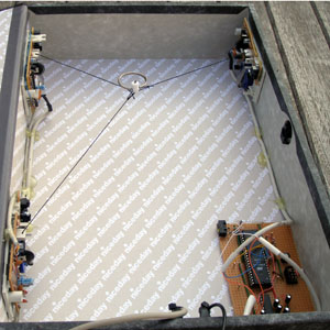 |
| The basic principle of Three Blind Mice is to run three threads round three rollers from old mechanical mice. By using the mouse reports to calculate the length of the extended thread this allows the position where all the threads join to be calculated. First job was to interface the mice to a PC. I am using old Microsoft Itellimice. The "z" axis on these mice which measures the position of the wheel is very low resolution and not suitable for this application. So, you need two mice to get the three axis of measurement required. It turns out that Windows makes it rather hard to extract input from individual mice if you have several connected to your PC. It is also rather tricky to override the normal mouse behaviour of moving the Windows cursor. Therefore rather than connect the mice directly to a PC I decided to interface the mice to an AVR microcontroller. The AVR then has a serial interface to the host PC. The PS/2 mouse interface is a bit of pain to work with, but with a bit of effort I was able to get things connected. | 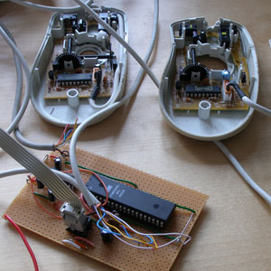 |
| With the electronics working I chose to use a box file as the fame for installing the mechanics. I like the idea of hiding this rather odd project inside this ordinary piece of stationary. I cut the mice to just keep enough of the PCB mounting and roller mecanism to meet my needs. For the third axis I introduced a third mouse with only acts as a mechanical frame and as a "remote" optical shaft-encoder for one of the two actually interfaced to the AVR. The original design uses simple weights to tension the cords. I wanted something more compact and portable. I decided to use spring-loaded retracting security badge clips. This photo shows one of the mice and the tensioning device (in fact this is the third-access without any active electronics). The cord is wrapped around the black horizontal roller and through a hole drilled in the plastic tab above the roller. As you can see HOT GLUE is an essential construction component on this project. For the software I decided to run the calculations to get the mouse position on the AVR. This means that the results don't need further processing (except for scaling) on the host PC. At this point a project I had thought might take a week at the beginning had taken more like a month. Still I had a 3D mouse and it actually works pretty well. The main problem is that that the data from the mice does drift leading to innaccurate absolute lenths for the location cords. As long as you don't make too sudden movements you can use it for several minutes without having to reset the reference point. I wrote a couple of little applications in VVVV to show off the mouse both as a camera positioning tool and also as a 3D drawing tool. The problem with camera positioning though is that you have no orientation data for the mouse. You basically can look at a fixed point from different angles, but not change where you are looking. In the back of my mind I came up with a solution to fix this limitation, and I knew that I couldn't rest until the job was done properly. So, with a heavy heart I embarked on part 2 of the Three Blind Mice project. | 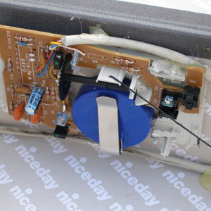 |
| Three Blind Mice Part 2 The aim of part 2 was to add orientation sensing to the original design. These days you can get a lot of chip-based solutions to sense orientation (except around the vertical axis). However I had an idea which was more in line with the spirit of the original design. An opto-mechanical mouse has two horizontal rollers at right angles to measure the ball's motion. My idea was to remove the ball and add off-centre weights to the rollers so that gravity makes the rollers always want to orient in one position. A bit of experimentation convinced me that this idea could give good enough results to be useful. On the photo you can see the two small nuts I fixed to the rollers. In the first stage of Part 2 I interfaced a third mouse to the AVR and doctored it as described to sense the orientation of the mouse against the horizontal plane. Amazingly it works really quite well! The last challenge therefore was to sense orientation around the vertical axis. To do this I mounted a shaft through the middle of the mouse and connected it to a shaft-encoder. This shaft encoder was connected to the spare on one of the original mice in part 1. Provided you can set some reference for the vertical axis in the mouse you can use this arrangement to get the mouse's orientation in all three dimensions. I should add at this point that the maths to translate from the mouse data to its orientation is mind bending. 3D rotation about arbitrary axis is not a pretty subject. | 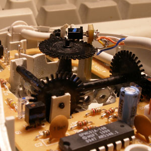 |
Phew! So, here we are at the end of the project. A full six axis 3D controller built from old computer mice. Eat your heart out Nintendo and Sony. This is the future. Demo software (running in background on the photo) allows the 3D mouse to control the camera view on a scene. You can pan around the scene any way and observe it from all angles. The 3D mouse is a little odd to start with, but once you get used to it then it actually becomes quite natural. Open the full screenshot from the thumbnail on the right. In the top left window is a red box which shows the position and orientation of the mouse. In the bottom left window you see a scene viewed from the point of view of the mouse. The right hand side is a VVVV patch to create these views. This is a project I am glad to be done with now. Much more hard work then I ever thought to start with, but I do love the fact that finally I got the results I wanted and only used scrap components. | 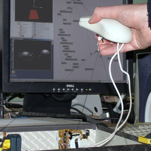 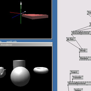 |
| Sourse: http://lushprojects.com/ |

No comments:
Post a Comment